Rod and Piston Gland Design for Basic Dynamic Applications
Dynamic o-rings with rod and piston gland designs are used for most basic dynamic applications. Dynamic o-rings are diverse, providing a wide range of uses, and selecting the right one for your application is key for achieving maximum o-ring performance. This dynamic o-ring groove design guide for rod and piston glands will help you find the dynamic o-ring that’s right for your application. Once you know the exact o-ring you need, you can quickly and easily order online from the world's largest inventory network.
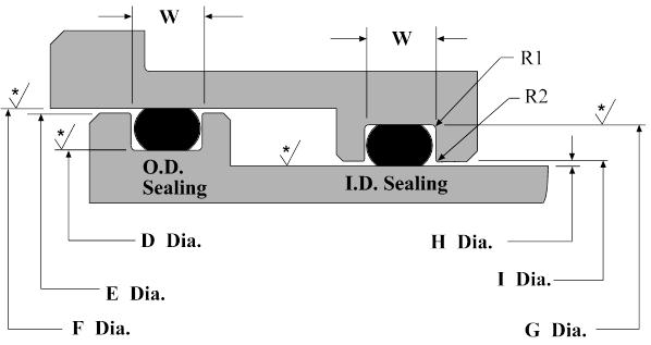
* Recommended surface finish: 16 Ra max. for gases and 32 Ra max. for fluids. All dynamic applications to have 16 Ra max.
Dynamic O-Ring Gland Width and Depth and Diameter Default Recomendations
| AS568 Dash Sizes | O-Ring Cross-Section |
Gland Width (W) |
Gland Corner Radii (Max.) |
|||
|---|---|---|---|---|---|---|
| dd | Nom. | Tol (+/-) | Nom. | Tol (+/-) | R1 | R2 |
| -0XX | 0.070 | 0.003 | 0.095 | 0.002 | 0.007 | 0.005 |
| -1XX | 0.103 | 0.004 | 0.142 | 0.003 | 0.007 | 0.005 |
| -2XX | 0.139 | 0.004 | 0.189 | 0.003 | 0.017 | 0.005 |
| -3XX | 0.210 | 0.005 | 0.283 | 0.003 | 0.027 | 0.005 |
| -4XX | 0.275 | 0.006 | 0.377 | 0.003 | 0.027 | 0.005 |
| Dash Size |
O-Ring Cross-Section |
O-Ring Diameter |
O.D. Sealing Type |
O.D. Sealing Type Piston Dia (E) |
O.D. Sealing Type Bore Dia (F) |
I.D. Sealing Type Gland Dia (G) |
I.D. Sealing Type Rod Dia (H) |
I.D. Sealing Type Bore Dia (I) |
||
|---|---|---|---|---|---|---|---|---|---|---|
| Nom | Tol +/- | Nom | Tol +/- | +.000 / -.002 | +.000 / -.001 | +.002 / -.000 | +.002 / -.000 | +.000 / -.002 | +.001 / -.000 | |
| -006 | 0.070 | 0.003 | 0.114 | 0.005 | 0.139 | 0.247 | 0.249 | 0.234 | 0.124 | 0.126 |
| -007 | 0.070 | 0.003 | 0.145 | 0.005 | 0.170 | 0.278 | 0.280 | 0.265 | 0.155 | 0.157 |
| -008 | 0.070 | 0.003 | 0.176 | 0.005 | 0.201 | 0.309 | 0.311 | 0.296 | 0.186 | 0.188 |
| -009 | 0.070 | 0.003 | 0.208 | 0.005 | 0.233 | 0.341 | 0.343 | 0.328 | 0.218 | 0.220 |
| -010 | 0.070 | 0.003 | 0.239 | 0.005 | 0.264 | 0.372 | 0.374 | 0.359 | 0.249 | 0.251 |
| -011 | 0.070 | 0.003 | 0.301 | 0.005 | 0.326 | 0.434 | 0.436 | 0.421 | 0.311 | 0.313 |
| -012 | 0.070 | 0.003 | 0.364 | 0.005 | 0.389 | 0.497 | 0.499 | 0.484 | 0.374 | 0.376 |
| Dash Size |
O-Ring Cross-Section |
O-Ring Diameter |
O.D. Sealing Type Gland Dia (D) |
O.D. Sealing Type Piston Dia (E) |
O.D. Sealing Type Bore Dia (F) |
I.D. Sealing Type Gland Dia (G) |
I.D. Sealing Type Rod Dia (H) |
I.D. Sealing Type Bore Dia (I) |
||
|---|---|---|---|---|---|---|---|---|---|---|
| Nom | Tol +/- | Nom | Tol +/- | +.000 / -.002 | +.000 / -.001 | +.002 / -.000 | +.002 / -.000 | +.000 / -.002 | +.001 / -.000 | |
| -104 | 0.103 | 0.003 | 0.112 | 0.005 | 0.136 | 0.310 | 0.312 | 0.300 | 0.124 | 0.126 |
| -105 | 0.103 | 0.003 | 0.143 | 0.005 | 0.167 | 0.341 | 0.343 | 0.331 | 0.155 | 0.157 |
| -106 | 0.103 | 0.003 | 0.174 | 0.005 | 0.198 | 0.372 | 0.374 | 0.362 | 0.186 | 0.188 |
| -107 | 0.103 | 0.003 | 0.206 | 0.005 | 0.230 | 0.404 | 0.406 | 0.394 | 0.218 | 0.220 |
| -108 | 0.103 | 0.003 | 0.237 | 0.005 | 0.261 | 0.435 | 0.437 | 0.425 | 0.249 | 0.251 |
| -109 | 0.103 | 0.003 | 0.299 | 0.005 | 0.323 | 0.497 | 0.499 | 0.487 | 0.311 | 0.313 |
| -110 | 0.103 | 0.003 | 0.362 | 0.005 | 0.386 | 0.560 | 0.562 | 0.550 | 0.374 | 0.376 |
| -111 | 0.103 | 0.003 | 0.424 | 0.005 | 0.448 | 0.622 | 0.624 | 0.612 | 0.436 | 0.438 |
| -112 | 0.103 | 0.003 | 0.487 | 0.005 | 0.511 | 0.685 | 0.687 | 0.675 | 0.499 | 0.501 |
| -113 | 0.103 | 0.003 | 0.549 | 0.007 | 0.573 | 0.747 | 0.749 | 0.737 | 0.561 | 0.563 |
| -114 | 0.103 | 0.003 | 0.612 | 0.009 | 0.636 | 0.810 | 0.812 | 0.800 | 0.624 | 0.626 |
| -115 | 0.103 | 0.003 | 0.674 | 0.009 | 0.698 | 0.872 | 0.874 | 0.862 | 0.686 | 0.688 |
| -116 | 0.103 | 0.003 | 0.737 | 0.009 | 0.761 | 0.935 | 0.937 | 0.925 | 0.749 | 0.751 |
| Dash Size |
O-Ring Cross-Section |
O-Ring Diameter |
O.D. Sealing Type Gland Dia (D) |
O.D. Sealing Type Piston Dia (E) |
O.D. Sealing Type Bore Dia (F) |
I.D. Sealing Type Gland Dia (G) |
I.D. Sealing Type Rod Dia (H) |
I.D. Sealing Type Bore Dia (I) |
||
|---|---|---|---|---|---|---|---|---|---|---|
| Nom | Tol +/- | Nom | Tol +/- | +.000 / -.002 | +.000 / -.001 | +.002 / -.000 | +.002 / -.000 | +.000 / -.002 | +.001 / -.000 | |
| -201 | 0.139 | 0.004 | 0.171 | 0.005 | 0.195 | 0.434 | 0.437 | 0.427 | 0.185 | 0.188 |
| -202 | 0.139 | 0.004 | 0.234 | 0.005 | 0.258 | 0.497 | 0.500 | 0.490 | 0.248 | 0.251 |
| -203 | 0.139 | 0.004 | 0.296 | 0.005 | 0.320 | 0.559 | 0.562 | 0.552 | 0.310 | 0.313 |
| -204 | 0.139 | 0.004 | 0.359 | 0.005 | 0.383 | 0.622 | 0.625 | 0.615 | 0.373 | 0.376 |
| -205 | 0.139 | 0.004 | 0.421 | 0.005 | 0.445 | 0.684 | 0.687 | 0.677 | 0.435 | 0.438 |
| -206 | 0.139 | 0.004 | 0.484 | 0.005 | 0.508 | 0.747 | 0.750 | 0.740 | 0.498 | 0.501 |
| -207 | 0.139 | 0.004 | 0.546 | 0.007 | 0.570 | 0.809 | 0.812 | 0.802 | 0.560 | 0.563 |
| -208 | 0.139 | 0.004 | 0.609 | 0.009 | 0.633 | 0.872 | 0.875 | 0.865 | 0.623 | 0.626 |
| -209 | 0.139 | 0.004 | 0.671 | 0.009 | 0.695 | 0.934 | 0.937 | 0.927 | 0.685 | 0.688 |
| -210 | 0.139 | 0.004 | 0.734 | 0.010 | 0.758 | 0.997 | 1.000 | 0.990 | 0.748 | 0.751 |
| -211 | 0.139 | 0.004 | 0.796 | 0.010 | 0.820 | 1.059 | 1.062 | 1.052 | 0.810 | 0.813 |
| -212 | 0.139 | 0.004 | 0.859 | 0.010 | 0.883 | 1.122 | 1.125 | 1.115 | 0.873 | 0.876 |
| -213 | 0.139 | 0.004 | 0.921 | 0.010 | 0.945 | 1.184 | 1.187 | 1.177 | 0.935 | 0.938 |
| -2147 | 0.139 | 0.004 | 0.984 | 0.010 | 1.008 | 1.247 | 1.250 | 1.240 | 0.998 | 1.001 |
| -215 | 0.139 | 0.004 | 1.046 | 0.010 | 1.070 | 1.309 | 1.312 | 1.302 | 1.060 | 1.063 |
| -216 | 0.139 | 0.004 | 1.109 | 0.012 | 1.133 | 1.372 | 1.375 | 1.365 | 1.123 | 1.126 |
| -217 | 0.139 | 0.004 | 1.171 | 0.012 | 1.195 | 1.434 | 1.437 | 1.427 | 1.185 | 1.188 |
| -218 | 0.139 | 0.004 | 1.234 | 0.012 | 1.258 | 1.497 | 1.500 | 1.490 | 1.248 | 1.251 |
| -219 | 0.139 | 0.004 | 1.296 | 0.012 | 1.320 | 1.559 | 1.562 | 1.552 | 1.310 | 1.313 |
| -220 | 0.139 | 0.004 | 1.359 | 0.012 | 1.383 | 1.622 | 1.625 | 1.619 | 1.373 | 1.376 |
| -221 | 0.139 | 0.004 | 1.421 | 0.012 | 1.445 | 1.684 | 1.687 | 1.677 | 1.435 | 1.438 |
| -222 | 0.139 | 0.004 | 1.484 | 0.015 | 1.508 | 1.747 | 1.750 | 1.740 | 1.498 | 1.501 |
| Dash Size |
O-Ring Cross-Section |
O-Ring Diameter |
O.D. Sealing Type Gland Dia (D) |
O.D. Sealing Type Piston Dia (E) |
O.D. Sealing Type Bore Dia (F) |
I.D. Sealing Type Gland Dia (G) |
I.D. Sealing Type Rod Dia (H) |
I.D. Sealing Type Bore Dia (I) |
||
|---|---|---|---|---|---|---|---|---|---|---|
| Nom | Tol +/- | Nom | Tol +/- | +.000 / -.002 | +.000 / -.001 | +.002 / -.000 | +.002 / -.000 | +.000 / -.002 | +.001 / -.000 | |
| -309 | 0.210 | 0.005 | 0.412 | 0.005 | 0.442 | 0.809 | 0.812 | 0.805 | 0.435 | 0.438 |
| -310 | 0.210 | 0.005 | 0.475 | 0.005 | 0.505 | 0.872 | 0.875 | 0.868 | 0.498 | 0.501 |
| -311 | 0.210 | 0.005 | 0.537 | 0.007 | 0.567 | 0.934 | 0.937 | 0.930 | 0.560 | 0.563 |
| -312 | 0.210 | 0.005 | 0.600 | 0.009 | 0.630 | 0.997 | 1.000 | 0.993 | 0.623 | 0.626 |
| -313 | 0.210 | 0.005 | 0.662 | 0.009 | 0.692 | 1.059 | 1.062 | 1.055 | 0.685 | 0.688 |
| -314 | 0.210 | 0.005 | 0.725 | 0.010 | 0.755 | 1.122 | 1.125 | 1.118 | 0.748 | 0.751 |
| -315 | 0.210 | 0.005 | 0.787 | 0.010 | 0.817 | 1.184 | 1.187 | 1.180 | 0.810 | 0.813 |
| -316 | 0.210 | 0.005 | 0.850 | 0.010 | 0.880 | 1.247 | 1.250 | 1.243 | 0.873 | 0.876 |
| -317 | 0.210 | 0.005 | 0.912 | 0.010 | 0.942 | 1.309 | 1.312 | 1.305 | 0.935 | 0.938 |
| -318 | 0.210 | 0.005 | 0.975 | 0.010 | 1.005 | 1.372 | 1.375 | 1.368 | 0.998 | 1.001 |
| -319 | 0.210 | 0.005 | 1.037 | 0.010 | 1.067 | 1.434 | 1.437 | 1.430 | 1.060 | 1.063 |
| -320 | 0.210 | 0.005 | 1.100 | 0.012 | 1.130 | 1.497 | 1.500 | 1.493 | 1.123 | 1.126 |
| -321 | 0.210 | 0.005 | 1.162 | 0.012 | 1.192 | 1.559 | 1.562 | 1.555 | 1.185 | 1.188 |
| -322 | 0.210 | 0.005 | 1.225 | 0.012 | 1.255 | 1.622 | 1.625 | 1.618 | 1.248 | 1.251 |
| -323 | 0.210 | 0.005 | 1.287 | 0.012 | 1.317 | 1.684 | 1.687 | 1.680 | 1.310 | 1.313 |
| -324 | 0.210 | 0.005 | 1.350 | 0.012 | 1.380 | 1.747 | 1.750 | 1.743 | 1.373 | 1.376 |
| -325 | 0.210 | 0.005 | 1.475 | 0.015 | 1.505 | 1.872 | 1.875 | 1.868 | 1.498 | 1.501 |
| -326 | 0.210 | 0.005 | 1.600 | 0.015 | 1.630 | 1.997 | 2.000 | 1.993 | 1.623 | 1.626 |
| -327 | 0.210 | 0.005 | 1.725 | 0.015 | 1.755 | 2.122 | 2.125 | 2.118 | 1.748 | 1.751 |
| -328 | 0.210 | 0.005 | 1.850 | 0.015 | 1.880 | 2.247 | 2.250 | 2.243 | 1.873 | 1.876 |
| -329 | 0.210 | 0.005 | 1.975 | 0.018 | 2.005 | 2.372 | 2.375 | 2.368 | 1.998 | 2.001 |
| -330 | 0.210 | 0.005 | 2.100 | 0.018 | 2.130 | 2.497 | 2.500 | 2.493 | 2.123 | 2.126 |
| -331 | 0.210 | 0.005 | 2.225 | 0.018 | 2.255 | 2.622 | 2.625 | 2.618 | 2.248 | 2.251 |
| -332 | 0.210 | 0.005 | 2.350 | 0.018 | 2.380 | 2.747 | 2.750 | 2.743 | 2.373 | 2.376 |
| -333 | 0.210 | 0.005 | 2.475 | 0.020 | 2.505 | 2.872 | 2.875 | 2.868 | 2.498 | 2.501 |
| -334 | 0.210 | 0.005 | 2.600 | 0.020 | 2.630 | 2.997 | 3.000 | 2.993 | 2.623 | 2.626 |
| -335 | 0.210 | 0.005 | 2.725 | 0.020 | 2.755 | 3.122 | 3.125 | 3.118 | 2.748 | 2.751 |
| -336 | 0.210 | 0.005 | 2.850 | 0.020 | 2.880 | 3.247 | 3.250 | 3.243 | 2.873 | 2.876 |
| -337 | 0.210 | 0.005 | 2.975 | 0.024 | 3.005 | 3.372 | 3.375 | 3.368 | 2.998 | 3.001 |
| -338 | 0.210 | 0.005 | 3.100 | 0.024 | 3.130 | 3.497 | 3.500 | 3.493 | 3.123 | 3.126 |
| -339 | 0.210 | 0.005 | 3.225 | 0.024 | 3.255 | 3.622 | 3.625 | 3.618 | 3.248 | 3.251 |
| -340 | 0.210 | 0.005 | 3.350 | 0.024 | 3.380 | 3.747 | 3.750 | 3.743 | 3.373 | 3.376 |
| -341 | 0.210 | 0.005 | 3.475 | 0.024 | 3.505 | 3.872 | 3.875 | 3.868 | 3.498 | 3.501 |
| -342 | 0.210 | 0.005 | 3.600 | 0.028 | 3.630 | 3.997 | 4.000 | 3.993 | 3.623 | 3.626 |
| -343 | 0.210 | 0.005 | 3.725 | 0.028 | 3.755 | 4.122 | 4.125 | 4.118 | 3.748 | 3.751 |
| -344 | 0.210 | 0.005 | 3.850 | 0.028 | 3.880 | 4.247 | 4.250 | 4.243 | 3.873 | 3.876 |
| -345 | 0.210 | 0.005 | 3.975 | 0.028 | 4.005 | 4.372 | 4.375 | 4.368 | 3.998 | 4.001 |
| -346 | 0.210 | 0.005 | 4.100 | 0.028 | 4.130 | 4.497 | 4.500 | 4.493 | 4.123 | 4.126 |
| -347 | 0.210 | 0.005 | 4.225 | 0.030 | 4.255 | 4.622 | 4.625 | 4.618 | 4.248 | 4.251 |
| -348 | 0.210 | 0.005 | 4.350 | 0.030 | 4.380 | 4.747 | 4.750 | 4.743 | 4.373 | 4.376 |
| -349 | 0.210 | 0.005 | 4.475 | 0.030 | 4.505 | 4.872 | 4.875 | 4.868 | 4.498 | 4.501 |
| Dash Size |
O-Ring Cross-Section |
O-Ring Diameter |
O.D. Sealing Type Gland Dia (D) |
O.D. Sealing Type Piston Dia (E) |
O.D. Sealing Type Bore Dia (F) |
I.D. Sealing Type Gland Dia| (G) |
I.D. Sealing Type Rod Dia (H) |
I.D. Sealing Type Bore Dia (I) |
||
|---|---|---|---|---|---|---|---|---|---|---|
| Nom | Tol +/- | Nom | Tol +/- | +.000 / -.002 | +.000 / -.001 | +.002 / -.000 | +.002 / -.000 | +.000 / -.002 | +.001 / -.000 | |
| -425 | 0.275 | 0.006 | 4.475 | 0.033 | 4.528 | 4.998 | 5.002 | 4.971 | 4.497 | 4.501 |
| -426 | 0.275 | 0.006 | 4.600 | 0.033 | 4.653 | 5.123 | 5.127 | 5.096 | 4.622 | 4.626 |
| -427 | 0.275 | 0.006 | 4.725 | 0.033 | 4.778 | 5.248 | 5.252 | 5.221 | 4.747 | 4.751 |
| -428 | 0.275 | 0.006 | 4.850 | 0.033 | 4.903 | 5.373 | 5.377 | 5.346 | 4.872 | 4.876 |
| -429 | 0.275 | 0.006 | 4.975 | 0.037 | 5.028 | 5.498 | 5.502 | 5.471 | 4.997 | 5.001 |
| -430 | 0.275 | 0.006 | 5.100 | 0.037 | 5.153 | 5.623 | 5.627 | 5.596 | 5.122 | 5.126 |
| -431 | 0.275 | 0.006 | 5.225 | 0.037 | 5.278 | 5.748 | 5.752 | 5.721 | 5.247 | 5.251 |
| -432 | 0.275 | 0.006 | 5.350 | 0.037 | 5.403 | 5.873 | 5.877 | 5.846 | 5.372 | 5.376 |
| -433 | 0.275 | 0.006 | 5.475 | 0.037 | 5.528 | 5.998 | 6.002 | 5.971 | 5.497 | 5.501 |
| -434 | 0.275 | 0.006 | 5.600 | 0.037 | 5.653 | 6.123 | 6.127 | 6.096 | 5.622 | 5.626 |
| -435 | 0.275 | 0.006 | 5.725 | 0.037 | 5.778 | 6.248 | 6.252 | 6.221 | 5.747 | 5.751 |
| -436 | 0.275 | 0.006 | 5.850 | 0.037 | 5.903 | 6.373 | 6.377 | 6.346 | 5.872 | 5.876 |
| -437 | 0.275 | 0.006 | 5.975 | 0.037 | 6.028 | 6.498 | 6.502 | 6.471 | 5.997 | 6.001 |
| -438 | 0.275 | 0.006 | 6.225 | 0.040 | 6.278 | 6.748 | 6.752 | 6.721 | 6.247 | 6.251 |
| -439 | 0.275 | 0.006 | 6.475 | 0.040 | 6.528 | 6.998 | 7.002 | 6.971 | 6.497 | 6.501 |
| -440 | 0.275 | 0.006 | 6.725 | 0.040 | 6.778 | 7.248 | 7.252 | 7.221 | 6.747 | 6.751 |
| -441 | 0.275 | 0.006 | 6.975 | 0.040 | 7.028 | 7.498 | 7.502 | 7.471 | 6.997 | 7.001 |
| -442 | 0.275 | 0.006 | 7.225 | 0.045 | 7.278 | 7.748 | 7.752 | 7.721 | 7.247 | 7.251 |
| -443 | 0.275 | 0.006 | 7.475 | 0.045 | 7.528 | 7.998 | 8.002 | 7.971 | 7.497 | 7.501 |
| -444 | 0.275 | 0.006 | 7.725 | 0.045 | 7.778 | 8.248 | 8.252 | 8.221 | 7.747 | 7.751 |
| -445 | 0.275 | 0.006 | 7.975 | 0.045 | 8.028 | 8.498 | 8.502 | 8.471 | 7.997 | 8.001 |
| -446 | 0.275 | 0.006 | 8.475 | 0.055 | 8.528 | 8.998 | 9.002 | 8.971 | 8.497 | 8.501 |
| -447 | 0.275 | 0.006 | 8.975 | 0.055 | 9.028 | 9.498 | 9.502 | 9.471 | 8.997 | 9.001 |
| -448 | 0.275 | 0.006 | 9.475 | 0.055 | 9.528 | 9.998 | 10.002 | 9.971 | 9.497 | 9.501 |
| -449 | 0.275 | 0.006 | 9.975 | 0.055 | 10.028 | 10.498 | 10.502 | 10.471 | 9.997 | 10.001 |
| -450 | 0.275 | 0.006 | 10.475 | 0.060 | 10.528 | 10.998 | 11.002 | 10.971 | 10.497 | 10.501 |
| -451 | 0.275 | 0.006 | 10.975 | 0.060 | 11.028 | 11.498 | 11.502 | 11.471 | 10.997 | 11.001 |
| -452 | 0.275 | 0.006 | 11.475 | 0.060 | 11.528 | 11.998 | 12.002 | 11.971 | 11.497 | 11.501 |
| -453 | 0.275 | 0.006 | 11.975 | 0.060 | 12.028 | 12.498 | 12.502 | 12.471 | 11.997 | 12.001 |
| -454 | 0.275 | 0.006 | 12.475 | 0.060 | 12.528 | 12.998 | 13.002 | 12.971 | 12.497 | 12.501 |
| -455 | 0.275 | 0.006 | 12.975 | 0.060 | 13.028 | 13.498 | 13.502 | 13.471 | 12.997 | 13.001 |
| -456 | 0.275 | 0.006 | 13.475 | 0.070 | 13.528 | 13.998 | 14.002 | 13.971 | 13.497 | 13.501 |
| -457 | 0.275 | 0.006 | 13.975 | 0.070 | 14.028 | 14.498 | 14.502 | 14.471 | 13.997 | 14.001 |
| -458 | 0.275 | 0.006 | 14.475 | 0.070 | 14.528 | 14.998 | 15.002 | 14.971 | 14.497 | 14.501 |
| -459 | 0.275 | 0.006 | 14.975 | 0.070 | 15.028 | 15.498 | 15.502 | 15.471 | 14.997 | 15.001 |
| -460 | 0.275 | 0.006 | 15.475 | 0.070 | 15.528 | 15.998 | 16.002 | 15.971 | 15.497 | 15.501 |