Our o-ring groove design guides list default o-ring groove dimensions for the most basic applications and are intended to be used with the following o-ring groove design considerations to engineer an o-ring gland to optimize specific application performance. The wrong size groove makes the best o-ring underperform.
Buy o-rings online from the world's largest o-ring inventory network.
|
O-Ring Squeeze Compression (O-Ring C/S) - Gland Depth / (O-Ring C/S) |
|
|
O-Ring Installed Stretch (Groove Diameter) - (O-Ring ID)(O-Ring ID) |
|
|
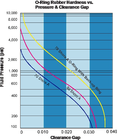
O-Ring Application Pressure Vs. O-Ring Gland Clearance Gap Size |
|
|
O-Ring Tolerances |
|
|
O-Ring Gland Surface Finish |
- 32Ra to seal liquid -16Ra to seal gas
|
|
O-Ring Gland Sharp Corners |
|
|
O-Ring Gland Fill % |
|
|
O-Ring Eccentricity & Side Loading |
|
High Pressure Extrusion
Most o-rings are designed to operate at pressures up to 1,500 psi. At higher pressures, the material must have enough strength to resist extruding into the clearance gap. The chart shows the recommended combined limits of clearance, gap, material hardness and system pressure differential. To avoid extrusion at high temperature, reduce the extrusion gap, increase the seal material hardness or add a back-up ring to the o-ring but will require a wider gland.
Pressure Cycling
Cycling pressure can cause the o-ring to move back and forth within the gland. This motion can damage seals with low abrasion resistant materials. A higher durometer or an abrasion resistant material is recommended for these applications.


